Conveyor belt tension is easy to overlook until the belt slips, wanders, or refuses to start. A correctly tensioned belt transfers drive power without excessive stress on pulleys, bearings, splices, and the belt itself. The practical question is simple: why is conveyor belt tension important? It affects safety, product flow, energy use, and maintenance costs every day.
In real inspections, I have seen operators tighten a belt until it felt “secure.” That approach can damage components. A belt may look stable while carrying too much tension near the drive pulley. Another belt may appear loose but operate correctly under its designed load. Measurement matters more than judgment by hand. Use the conveyor manufacturer’s instructions, approved tension values, and suitable measuring tools. Check belt tracking, pulley alignment, take-up position, and loading conditions together. Small details matter, such as material buildup under a return roller or a cold belt stiffening during startup.
This guide explains how to set conveyor belt tension with a controlled, repeatable method. It also connects tension settings with common symptoms, including slippage, edge wear, mistracking, and premature splice failure. Experienced technicians know that one adjustment rarely solves everything. I should add a caution: field conditions can differ from the original design. Temperature, belt age, humidity, and changing loads may alter the result. Recheck the system after adjustment, record the reading, and watch the belt during operation. A careful setup is not perfect forever. It is a measured starting point.
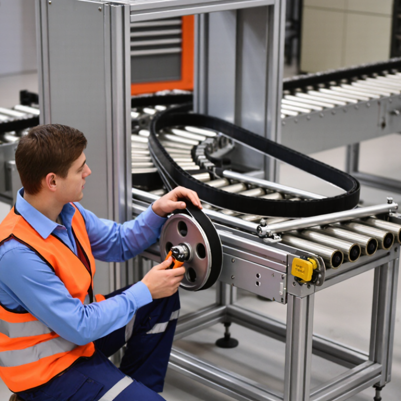
Belt tension is the pulling force carried through the conveyor belt. Take-up force creates this tension by moving the tail or take-up pulley. Pre-tension is the initial force applied before material enters the conveyor. It removes slack and helps the belt track correctly.
Too little tension causes slipping, wandering, and pulley lag. Too much tension can damage splices, bearings, and the belt carcass. Keep it practical.
A useful field check is belt sag. Measure the vertical drop between two neighboring idlers while the belt is stopped and unloaded. Aim for about 1–3% of the idler spacing.
With a one-meter spacing, that means roughly 10–30 millimeters of sag.
Less sag may indicate excessive pre-tension. More sag can signal insufficient take-up force or belt stretch.
Mark the belt before adjustment. This makes movement easier to verify.
Adjust the take-up gradually, using equal turns on both sides. Recheck tracking after every small change. Listen for squealing at the drive pulley, and inspect the splice for unusual strain.
I have seen operators tighten a loose belt until the original slipping stopped, then create bearing heat within an hour. That approach was too aggressive.
Temperature, load, belt length, and splice condition all affect the correct setting. A tension gauge or manufacturer’s calculation is more reliable than hand judgment alone. Local measurements still matter. Each conveyor behaves differently.
Before adjusting conveyor belt tension, gather dependable operating data. Guesswork often causes tracking problems, slipping, or unnecessary belt stress. Measure the belt width in millimeters and record the belt mass per meter. Include belt covers, fasteners, and any attached components. These details affect the force required to move the belt. Keep the numbers visible.
Measure the belt speed during normal production, not only during an empty test. A loaded belt can behave differently. Record the conveyor length from pulley center to pulley center. Longer systems usually need more careful tension control because stretch becomes more noticeable. Material load also matters. Weigh a typical load, then note its moisture, size, and distribution. Wet material can cling to the belt and increase resistance. Uneven loading creates changing tension across the belt.
I once used an empty-belt reading that looked correct, but the belt slipped after loading. The missing detail was material buildup near the discharge area. Small mistakes matter. Use the gathered width, mass, speed, length, and load values in the tension calculation recommended by the equipment’s technical documentation. Then compare the calculated value with field conditions. Apply adjustments gradually, while checking belt tracking, pulley contact, and drive response. Too little tension encourages slip. Too much tension increases bearing and splice stress. Recheck the measurements after the conveyor reaches normal temperature, because thermal expansion can change the result.
Conveyor belt tension should be calculated while the system is running, not guessed from the take-up position. CEMA’s Belt Conveyors for Bulk Materials, 7th Edition, separates resistance, elevation, acceleration, and drive effects. DIN 22101:2011 follows the same engineering logic.
Use this practical calculation: Fe = Fres + Finc + Facc. Resistance is Fres = fmg cos θ. Incline force is Finc = mg sin θ. Acceleration force is Facc = ma. Here, m includes the belt and conveyed load. For a 1,200-kilogram moving mass, a 6-degree incline, a 0.03 resistance factor, and 0.2 m/s² acceleration, the forces are approximately 346, 1,232, and 240 newtons. The effective pull is therefore about 1,818 newtons.
Drive tension still depends on friction and belt wrap. Using T1 = Fe ÷ (1 − e−μθ), with μ = 0.25 and 210 degrees of wrap, tight-side tension reaches roughly 3,030 newtons. Slack-side tension is about 1,212 newtons. With a 400-millimeter drive pulley and 90% efficiency, required drive torque is approximately 404 newton-metres. These values are calculated examples, not universal settings. Real installations need measured belt mass, material loading, pulley condition, and starting behavior. I have seen tension rise sharply when a damp loading zone adds resistance. That detail is easy to miss. CEMA and DIN methods should guide the calculation, while field measurements confirm it.
| Category | Parameter | Symbol | Value | Unit | Calculation or Engineering Meaning |
|---|---|---|---|---|---|
| Conveyor Design Inputs | |||||
| Geometry | Conveyor center-to-center length | L | 120 | m | Horizontal belt travel length used for mass and resistance calculations. |
| Geometry | Incline angle | θ | 8 | degrees | Positive angle indicates that the conveyor lifts the material. |
| Geometry | Vertical lift | H | 16.7 | m | H = L × sin(θ) = 120 × sin(8°). |
| Capacity | Material mass per unit length | mm | 40 | kg/m | Represents approximately 4,800 kg of material on the loaded carrying strand. |
| Belt | Belt mass per unit length | mb | 18 | kg/m | Applied to both the carrying and return strands. |
| Drive | Belt speed | v | 1.5 | m/s | Used to estimate the continuous drive power requirement. |
| Resistance | Effective rolling resistance coefficient | f | 0.030 | dimensionless | Representative value for a maintained belt conveyor with rolling idlers. |
| Drive | Drive pulley wrap angle | β | 210 | degrees | Wrap angle converted to 3.665 radians for the traction calculation. |
| Drive | Belt-to-pulley friction coefficient | μ | 0.25 | dimensionless | Representative dry-contact value; actual performance depends on surface and conditions. |
| Drive | Mechanical efficiency | η | 0.90 | dimensionless | Includes approximate gearbox, bearing, and drive transmission losses. |
| Resistance | Additional fixed resistance allowance | Fa | 0.50 | kN | Allowance for skirt friction, cleaners, pulley bearings, and other secondary resistances. |
| Running Tension Calculation | |||||
| Mass | Total belt mass on both strands | Mb | 4,320 | kg | Mb = 2 × L × mb = 2 × 120 × 18. |
| Mass | Material mass on the loaded strand | Mm | 4,800 | kg | Mm = L × mm = 120 × 40. |
| Resistance | Total moving mass used for rolling resistance | Mt | 9,120 | kg | Mt = Mb + Mm. |
| Resistance | Rolling and idler resistance | Fr | 2.68 | kN | Fr = f × Mt × g = 0.030 × 9,120 × 9.81. |
| Resistance | Incline lifting force | Fi | 6.55 | kN | Fi = Mm × g × sin(θ) = 4,800 × 9.81 × sin(8°). |
| Resistance | Additional fixed resistance | Fa | 0.50 | kN | Allowance included to avoid understating the required effective tension. |
| Drive | Effective drive force | Te | 9.74 | kN | Te = Fr + Fi + Fa = 2.68 + 6.55 + 0.50. |
| Traction | Maximum theoretical tension ratio | T1/T2 | 2.50 | ratio | T1/T2 = e(μβ) = e(0.25 × 3.665). |
| Tension | Slack-side running tension | T2 | 6.49 | kN | T2 = Te / [(T1/T2) − 1] = 9.74 / 1.50. |
| Tension | Tight-side running tension | T1 | 16.23 | kN | T1 = T2 + Te = 6.49 + 9.74. |
| Drive Power and Belt Tension Checks | |||||
| Power | Continuous power at the drive pulley | Pshaft | 14.6 | kW | Pshaft = Te × v = 9.74 × 1.5. |
| Power | Estimated input power before service margin | Pinput | 16.2 | kW | Pinput = Pshaft / η = 14.6 / 0.90. |
| Belt | Nominal belt width | B | 650 | mm | Used to express tight-side tension as force per unit belt width. |
| Belt | Tight-side tension per unit width | T1/B | 25.0 | N/mm | T1/B = 16,230 N / 650 mm. |
| Setting | Recommended tensioning objective | — | Maintain calculated running tension | — | Set take-up tension high enough to prevent slip and excessive sag, but not higher than the belt, splice, pulley, and structure allow. |
| Verification | Final allowable tension check | — | Required before commissioning | — | Compare the calculated 25.0 N/mm with the belt supplier's allowable running tension, splice rating, start-up tension, and applicable safety requirements. |
| Illustrative engineering example using rounded SI values. Actual tension settings should be verified using measured belt sag, start-up conditions, temperature, loading profile, pulley lagging, belt construction, and site-specific resistance data. | |||||
Correct belt tension starts with take-up travel, not a hurried adjustment at the tail pulley. On a running conveyor, I check the take-up position, belt tracking, and splice condition. Leave enough travel for future stretch and thermal movement. A take-up parked at its limit has little room to compensate. That mistake is common. It can cause slip, mistracking, or excessive pulley load. Lock out the equipment and verify zero energy before entering the conveyor area.
Set initial belt elongation between 0.5% and 1.5%, unless the belt’s engineering data requires another value. Measure a clearly marked belt section before tensioning. Measure it again under the prescribed operating tension. The calculation is simple: elongation equals the length increase divided by the original length, multiplied by 100. For example, a 10-meter section extending 100 millimeters equals 1%. Use a steel tape, not a guess. Keep measurements at the same temperature and belt condition.
After adjustment, run the conveyor empty, then under normal load. Watch for belt sag, pulley slip, bearing temperature, and take-up movement. Recheck the marks after several operating cycles. A belt may settle more than expected. I have seen teams tighten belts repeatedly because they measured a dirty reference mark. Clean the surface and record each reading. Do not chase perfect numbers while ignoring tracking or splice condition. Tension is only one part of the system.
Set the take-up travel correctly and verify that the belt elongation remains within the recommended 0.5–1.5% range. Excessive elongation can cause belt slip, tracking problems, and premature wear.
How to read the chart: Compare the measured belt elongation with the 0.5–1.5% acceptable operating range. If elongation is below the range, traction may be insufficient; if it exceeds the range, inspect belt condition, take-up settings, and splice integrity.
After tension adjustment, check tracking before increasing speed. A belt drifting toward one frame usually signals uneven tension, misaligned idlers, or material buildup. The CEMA Belt Conveyors for Bulk Materials handbook recommends controlled, measured adjustments rather than aggressive take-up movement. Make small changes, then observe the belt through several complete revolutions. Watch the return strand too. It often reveals problems first.
Slippage leaves dark polish marks beneath the drive pulley. It may also create a hot rubber smell. Measure belt speed against pulley speed when possible. A slipping belt wastes energy and can damage the cover. The U.S. Department of Energy’s Motor Systems Market Assessment reports that motor systems consume about 68% of manufacturing electricity. Conveyor losses therefore deserve attention, even when the motor still runs normally.
Check both bearing temperature and sound after adjustment. Excessive tension can raise bearing load, while insufficient tension encourages slip. Compare readings with the machine’s baseline, not memory. Then review motor current under the normal material load. Current that rises without higher throughput deserves investigation. I have seen teams stop after tracking looked correct. That was not enough. Recheck fasteners, pulley lagging, and take-up travel after a short production run. A perfect adjustment on an empty belt can behave differently under wet, uneven material. The mistake is common. It is also preventable.
Belt tension is the pulling force carried through the belt. Take-up movement creates this force. Pre-tension removes slack before loading begins.
Too little tension can cause slipping, wandering, and poor pulley grip. Too much tension may damage splices, bearings, or the belt carcass. More tightening is not always better.
Aim for about 1–3% of the spacing between neighboring idlers. With one-meter spacing, sag should measure roughly 10–30 millimeters. Measure the vertical drop with the belt stopped and unloaded.
Very little sag may indicate excessive pre-tension. Excessive sag can suggest weak take-up force or belt stretch. Mark the belt before adjustment.
Turn both sides equally and make small adjustments. Recheck tracking after every change. Listen for drive-pulley squealing and inspect the splice.
Hand judgment can mislead. A tension gauge or engineering calculation is more dependable. Local checks still matter because each conveyor behaves differently.
Estimate effective pull from resistance, incline, and acceleration forces. A practical relationship is Fe = Fres + Finc + Facc. The calculation should include belt mass and conveyed material.
For a 1,200-kilogram moving mass, the estimated effective pull is about 1,818 newtons. Drive friction and belt wrap then affect tight-side tension. These figures are examples, not universal settings.
Damp loading areas can increase resistance and raise tension sharply. Temperature, belt length, load, pulley condition, and starting behavior also matter. I would not ignore a wet loading zone.
Proper conveyor belt tension is essential for stable, efficient, and safe operation. To understand why is conveyor belt tension important, start by distinguishing take-up force, pre-tension, and the recommended 1–3% belt sag between supports. Before making any adjustment, gather accurate operating data, including belt width, belt mass, conveying speed, conveyor length, and material load. These factors provide the foundation for estimating running tension and selecting an appropriate take-up setting.
Running tension should account for belt resistance, incline forces, and drive forces under normal load. Set sufficient take-up travel to accommodate movement and aim for approximately 0.5–1.5% belt elongation, avoiding both excessive tightness and inadequate tension. After adjustment, inspect belt tracking, check for slippage, examine bearings, and monitor motor load. A properly tensioned belt improves power transmission, reduces unnecessary wear, and supports consistent material flow while helping prevent premature component failure.

Trakkx Tech